


")


Boston is alive.
It’s a hustling. bustling, melting pot of culture. The local Bostonian accent hits you thick and fast, and the less initiated have to double take for a response. If you prick your ears up, you’ll easily hear 5 different languages a day. Ethnic cuisine finds itself at every street corner, including the inauthentic (but tasty) General Gao’s Chicken, the curious American cousin of sweet and sour pork.
Culture isn’t just evident in the people. The architecture and geography carry with them the history of decades past. You’ll find place names carbon copies of locales in Britain, while buildings sporting Gothic, Modern and Baroque styles stand side by side.
It’s the city of eternal gridlock, and when traffic isn’t at a complete standstill, you might miss the stealthy Tesla slip by you on the street. Or you might catch a fire engine scream by. Or five. At 5.30 am.
 But we didn’t come here to be deafened by emergency vehicles, we came to build boats! I had the privilege of being placed in a fantastic, innovative team, and we decided early on that building an ordinary boat was out of the question.
We agreed to build an amphibious boat – one that could travel on both land and water (in style). We certainly didn’t want a conventional duck boat, with separate propulsion methods for land and sea. We wanted a novel, integrated solution, and it just had to look cool.
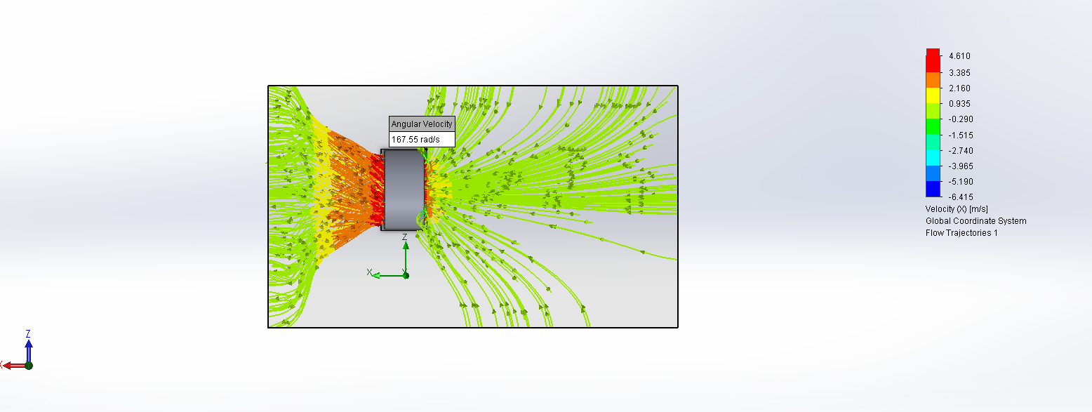
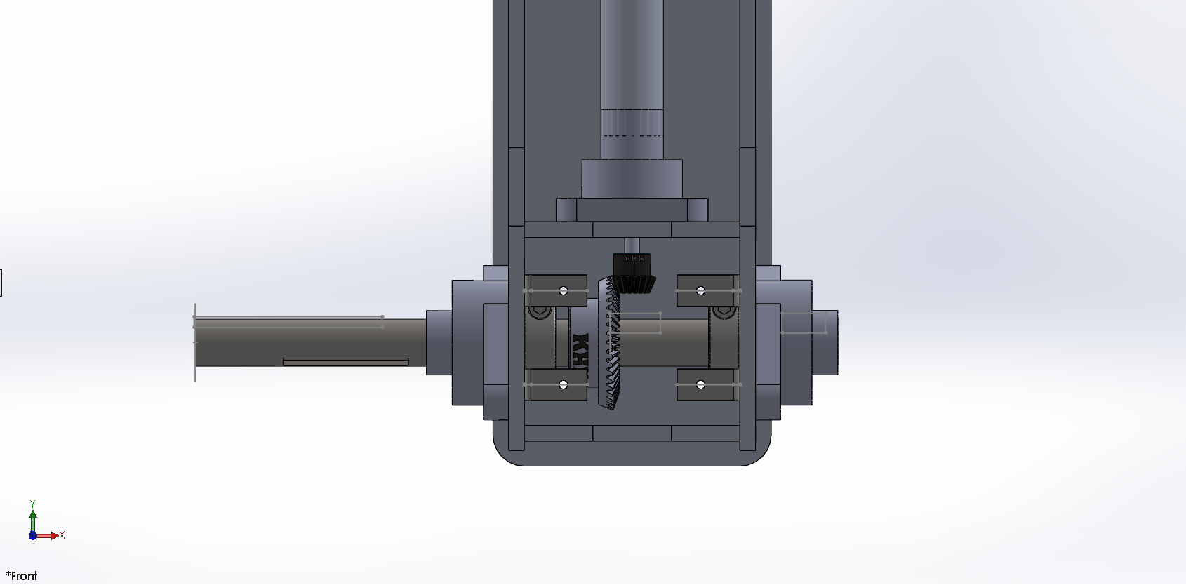
Given our tight budget and tighter timeline, we had to compromise smart. One thing we really didn’t want to compromise on, was our wheel/propeller hybrid.
Having an integrated unit meant the entire drive train had to point in two different directions for land and sea travel. Our initial design incorporated 2 universal joints for power transmission, which allowed the entire hub-bearing assembly to swing -45 to +45 degrees.
There were multiple flaws with this solution, chief of which were that universal joints do not transmit power at a constant rotational velocity. Also, this design required the drive shaft to pierce the boat’s hull, an additional step we did not have the time to engineer for.
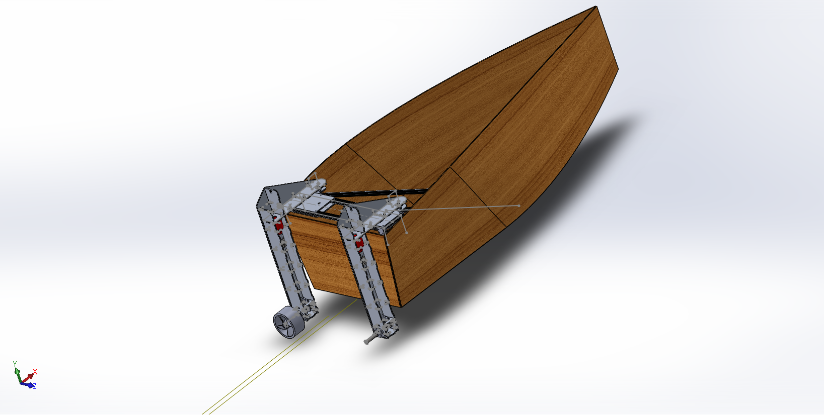
Back to the drawing board, then. We wound up placing our entire drive train into an outboard-style motor, where the entire assembly hung off the outside of the boat.
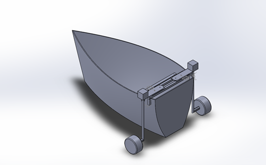
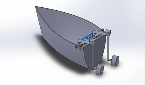
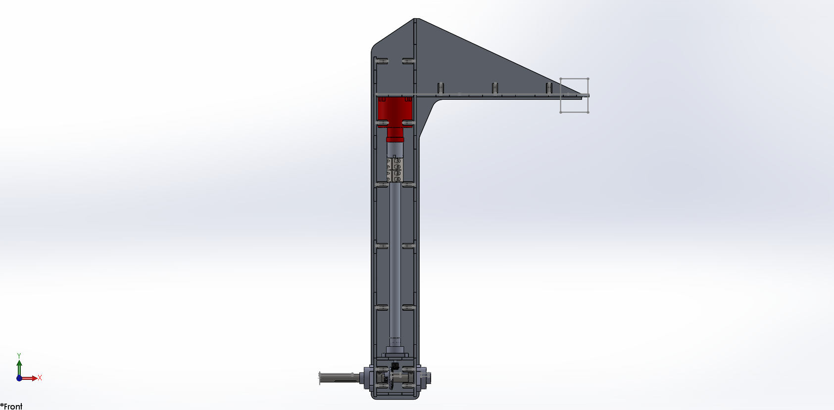
This design was risky. The outboard units had to support the weight of the hull, driver, power electronics, etc. Shearing forces were a huge concern. After much back and forth, designing, re-designing, and re-re-designing, we wound up with this almost final design:
As I write this, we’re in the midst of fabricating all our metal parts, ready for assembly and testing by the end of the week. I’d be happy to go into further detail, but I think this post covers most of the basics.
It’s been a blast so far. Learnt a lot, seen a lot, ate a lot. Like most experiences however, you’re going to forget most of it in time.
It’s the connections and friendships you build – and continue to build – that stay with you the longest.


